What the interface gate closes
An interface is more than a plug or mounting pattern. It is a boundary where two
parts of the mission system exchange load, energy, information, control, or
human action. The aircraft and payload may share several such boundaries at
once: structural attachment, electrical power, thermal paths, data transport,
time, position and attitude metadata, control commands, crew procedures, and the
final data workflow.
NASA's systems-engineering guidance treats interface management as the work of
defining functional, physical, and performance boundaries; identifying their
physical, electrical, mechanical, and human characteristics; maintaining
configuration documentation; and verifying compatibility. It also connects
interface control directly to verification and validation. That is the useful
principle behind the gate, although a small UAS program should tailor the
process to its own scale and authority rather than copy NASA program machinery.
NASA's interface-management chapter
provides the underlying source.
For this framework, a row closes only when seven items agree:
- Requirement: what the integrated system must do or avoid.
- Boundary: exactly where the exchange occurs and what lies on each side.
- Owner: the role responsible for defining and resolving that boundary.
- Configuration: the hardware, software, settings, installation, and
operating state to which the decision applies.
- Method: analysis, inspection, demonstration, test, or a justified
combination.
- Evidence: a recoverable result tied to the requirement and configuration.
- Acceptance: the authorized disposition of the result and any deviation.
"Compatible" is therefore a conclusion supported by this record, not an input to
it. A vendor compatibility list can help define the starting configuration, but
it does not close mission, installation, environment, or evidence questions.
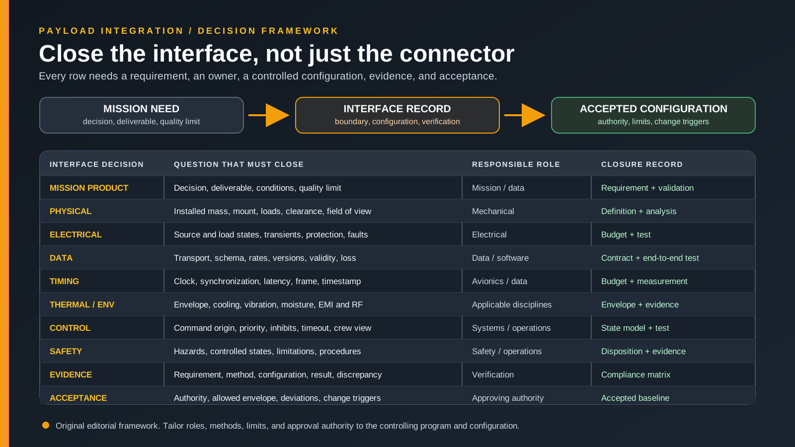
The ten-row payload integration-gate matrix
The table is a review framework, not a universal assignment of job titles. A
small team may place several roles with one person. A larger program may divide
them among specialists. What matters is that each decision has an identified
owner and an acceptance authority before testing begins.
Scroll horizontally to compare all columns.
This matrix adds a discipline that ordinary checklists often omit: evidence and
acceptance are separate decisions. A test team can produce valid evidence
without having authority to accept a deviation. An approving authority can make
a disposition only after the requirement, configuration, and evidence are clear.
Start with the mission product, not the sensor
"Integrate a thermal camera" names equipment. It does not state the decision the
system must support. A useful mission requirement begins with the observable
condition, deliverable, collection context, metadata, quality limits, and the
person or process that will interpret the result. That statement drives the
payload mode, field of view, timing, positioning, storage, flight profile, and
post-processing requirements.
This distinction also separates verification from validation. Verification asks
whether the realized configuration meets its specified requirements. Validation
asks whether the resulting system and product meet the intended use. A camera
can pass an electrical and data test while its collected product remains unfit
for the intended decision. The
aerial inspection evidence framework
develops the related distinction among observation, measurement, and diagnosis.
Before selecting an interface method, record at least:
- the decision and intended user of the product;
- the target features or events that must be observable;
- required coverage and material spatial or temporal limits;
- allowable missing, stale, or invalid data;
- required time, position, attitude, and calibration context;
- environmental and operational conditions in which the result is expected;
- the acceptance method for the final deliverable.
These are not necessarily aircraft requirements yet. They are the source from
which aircraft, payload, data, and operating requirements can be allocated. If
the team cannot state the mission product, it cannot know whether the integrated
system has succeeded.
Close the physical installation as a configuration
The physical row covers the installed system, not the payload's catalog mass.
Include the mount, fasteners, adapters, cables, strain relief, enclosure,
protective hardware, and any ballast. Evaluate the resulting mass properties
through the operating states that can change them. Define the three-dimensional
envelope for installation, normal motion, landing, maintenance, emergency
access, airflow, and all required fields of view.
Attachment is also a load path. The controlling review may need to address
strength, stiffness, retention, vibration isolation, fastener locking, cable
loads, and the consequence of a partial failure. An external installation can
also affect drag, airflow, antenna patterns, sensor visibility, and handling.
Which analyses or approvals are required is platform-specific. The gate should
identify the applicable limit and responsible authority rather than assume that
a successful fit check resolves it.
The
SIERRA-B Experimenters Handbook, Revision B
is a useful public example of configuration specificity. It documents payload
volumes, mass and balance constraints, acceleration loads, vibration
environments, moisture considerations, interface drawings, and location-based
electromagnetic conditions for NASA's SIERRA-B aircraft. None of its numerical
limits transfers to another UAS. The transferable lesson is that these
characteristics are related parts of one installation definition.
The physical row should identify the drawing or controlled installation record,
the payload and mounting revisions, the required inspections, any supporting
analysis, and the allowed operating envelope. A photograph can support an
inspection record, but it does not replace dimensions, load analysis, or a
configuration identifier.
Separate electrical capacity from electrical compatibility
Average power is only one electrical question. Define the source at the payload
boundary and the load in every relevant state: off, startup, initialization,
idle, active collection, actuator movement, transmit, recording, shutdown, and
fault. Record allowable voltage, steady and transient current, inrush behavior,
sequencing, grounding and bonding, isolation, circuit protection, load shedding,
and what occurs after a brownout or abrupt power removal.
The source and load budgets should use controlling limits, not a connector's
apparent rating or a nominal nameplate value. If the aircraft can provide more
than one power mode, the interface record should state which mode is enabled,
how it is requested, and which configuration controls that request. If a
converter or battery is added, its efficiency, heat, protection, energy state,
and failure behavior become part of the integrated system.
SIERRA-B again provides an attributed example, not a general prescription. Its
handbook states that aircraft-fed payload loads for that platform must be fused
and fail safe after a blown fuse, load shedding, or temporary or total power
loss. It also describes source-dependent ripple, transients, offsets, dropouts,
and noise. Those details show why "24 V" alone would be an incomplete interface
statement.
Wiring construction deserves the same configuration discipline. SIERRA-B calls
for its harnesses to follow NASA-STD-8739.4. The
current NASA standards record for NASA-STD-8739.4A with Change 4
defines that standard's scope as critical NASA cable and harness work. It is not
a universal commercial-UAS mandate. The general lesson is to identify the
workmanship, inspection, connector, pinout, shielding, routing, and retention
requirements that actually apply to the project instead of leaving "make a
cable" as an uncontrolled task.
Define data and timing as independent interfaces
A shared physical connector or transport name does not define an application
interface. Ethernet, USB, CAN, and serial links still need compatible electrical
implementations, roles, message formats, addressing, rates, units, byte order,
quality indicators, retry or acknowledgement behavior, and loss handling.
Software and firmware versions can be as consequential as the cable.
Manufacturer documentation can establish a product-specific starting point. For
example, DJI's current
Payload SDK aircraft-port documentation
attributes different structural forms, interface definitions, power support, and
functions to E-Port and E-Port V2, with support mapped to particular aircraft.
That is evidence about the documented DJI configurations only. It is also a
concrete reason to record aircraft model, port generation, adapter, pinout, SDK,
and software version rather than treating an ecosystem name as a compatibility
guarantee.
Build a data contract for each exchange:
- origin, destination, direction, and authorization;
- physical and transport layers plus the application schema;
- expected, maximum, and burst rates under defined modes;
- units, scaling, reference frames, and validity flags;
- buffering, storage, retention, and behavior after loss or reconnection;
- version negotiation, dependencies, update, and rollback method;
- health reporting, fault codes, stale-data indication, and recorded logs.
Time needs its own row because data can arrive correctly and still be associated
with the wrong event or pose. Record the clock source, synchronization method,
timestamp creation point, expected offset and drift, transport latency, exposure
or sample timing, position and attitude epoch, and handling of an invalid clock.
The evidence must support the timing need of the mission product. A packet's
arrival time is not automatically the sensor's observation time.
If command and control, aircraft telemetry, payload commands, preview video, and
recorded payload data share a transport or radio, keep their functions and
priorities distinct. The
UAS data-link roles guide provides a separate
map for that allocation. Payload throughput should not be allowed to hide or
starve a safety-significant control or status path.
Treat thermal, environment, and interference as operating states
Environmental compatibility is not a single bench condition. Define the relevant
states from installation and ground checks through flight, shutdown, storage,
and removal. Consider temperature, available airflow, solar loading, moisture or
condensation, dust, pressure when relevant, acceleration, shock, vibration,
acoustics, and the duration and sequence of exposure.
Thermal review should trace where heat is generated, conducted, stored, and
rejected. A configuration cooled adequately in flight can face a different case
during a long powered ground check. A protective enclosure can change both
cooling and sensor performance. The closure evidence might combine component
limits, analysis, temperature measurements, and an operating limitation. The
method and margins must come from the controlling project, not this framework.
Electromagnetic compatibility is bidirectional. Aircraft radios, motors,
switching converters, and digital electronics can affect a payload or its
measurements. A payload transmitter, processor, cable, or converter can affect
navigation, command links, receivers, or other aircraft systems. The interface
record should identify relevant frequencies, operating modes, antenna and cable
locations, shielding and grounding, simultaneous transmit states, and the
measurements or tests used to accept coexistence. A quiet payload bench does not
reproduce an integrated aircraft's electromagnetic environment.
Allocate control authority before writing commands
Payload control has two directions. The aircraft or crew may point, trigger,
configure, power, or inhibit the payload. The payload or its mission computer
may request aircraft position, attitude, route, speed, or another behavior.
Those paths should not be hidden inside a generic "data" interface.
For every command, state:
- which human or system may originate it;
- which modes make it valid;
- whether acknowledgement means receipt, acceptance, or completed action;
- what timeout, retry, stale-command, and duplicate-command behavior applies;
- which command has priority when sources disagree;
- which limits or inhibits cannot be overridden through the payload path;
- what the crew sees and can do when the payload or command path fails.
This is an allocation of authority, not merely an API description. If software
can select or change aircraft behavior based on payload data, the system review
must define the decision boundary and human responsibility. The
automation and autonomy authority test
offers a companion framework for examining that allocation without treating all
automated functions as autonomy.
Safety review then asks what hazards arise from the integrated configuration and
how each is controlled. Relevant conditions may include insecure attachment,
obstructed aircraft sensors, unexpected center-of-gravity change, electrical
fault, excess temperature, actuator runaway or jam, inadvertent emission,
corrupted command, stale metadata, loss of payload data, and misleading crew
status. The response may be a design control, isolation, automatic state,
warning, limitation, procedure, or a justified combination. "Fail safe" is not
complete until the safe state, trigger, timing, authority, and evidence are
defined.
For operations under US 14 CFR part 107,
section 107.49(e)
requires the remote pilot in command, before flight, to ensure that an attached
or carried object is secure and does not adversely affect flight characteristics
or controllability. That operational minimum does not itself verify the design,
approve a modification, or resolve other applicable requirements.
Match evidence to the claim
NASA describes verification as confirmation that specified requirements are met,
using analysis, inspection, demonstration, or test. Its
product-verification guidance
also calls for results to be traced in a compliance or verification matrix,
discrepancies to be resolved, and reports to identify the requirement, method,
configuration, result, and corrective action. The framework adopts that evidence
logic, not NASA's program-specific approval structure.
Choose the method that can actually support the claim:
Scroll horizontally to compare all columns.
A bench test is valuable when its scope is explicit. It can close pinout,
sequencing, message, and some power questions. It generally cannot, without
additional evidence, close aircraft controllability, structural loads, cooling
in representative flight states, electromagnetic coexistence, or the quality of
the final mission product. The test record should say both what passed and what
remains outside its boundary.
Close a configuration, then control change
The gate closes one defined configuration. Record aircraft identifier or
applicable configuration, payload hardware and firmware, mount and harness
revisions, software and parameter sets, data schema, time source, operating
modes, approved procedures, limitations, and the evidence package. Use a clear
status for each row: closed, closed with an accepted deviation, open, or not
applicable with rationale.
Acceptance should answer four questions:
- Which exact configuration and mission envelope may proceed?
- Who has authority to accept each result or deviation?
- Which limitations and crew actions travel with the configuration?
- Which changes require review and re-verification?
Likely re-opening triggers include a different payload or aircraft revision,
mount or cable change, material mass-property change, power-source change,
software or firmware update, new data schema, clock or synchronization change,
new command authority, changed duty cycle, expanded environment, or different
mission product. Reopen the affected row and every dependent row. Do not rerun
irrelevant work merely for ceremony, and do not preserve a green status after
its supporting configuration has changed.
A concise gate packet can therefore contain the mission requirement, controlled
interface record, installation definition, power and data budgets, timing and
authority models, hazard dispositions, verification matrix, discrepancy log,
crew limitations, and final acceptance record. Its size can be tailored. Its
traceability cannot be optional if the decision is meant to survive a handoff,
software update, maintenance action, or later incident review.
The final close-or-stop rule is simple: proceed only when every applicable row
has an accepted requirement, evidence tied to the intended configuration, and a
named authority willing to close it. If the payload merely fits, powers on, or
streams data, integration has started. It has not yet passed the interface gate.